Introduction
This week was about Output devices, I had to do one board with an output. I did the LCD board, since it will be part of my final project and the stepper motor one, since it was part of my machine project.
Documentation
I did the most part of my studies during the input devices week, so basically I
studied this assignment schedule very well, I looked at the boards, and I read
tons of datasheets. In order to develop better skills using Eagle I looked
for some tutorial on youtube, I've found this one:
It's a tutorial for beginners, but still it was pretty useful to me. The most part of
the things I've learned about this software came from direct experience on it.
This tutorial helped me to have a better idea about its workflow in genearl.
LCD
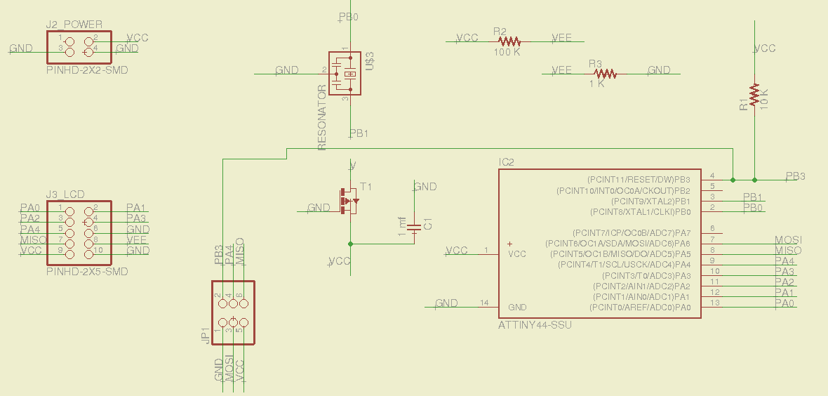
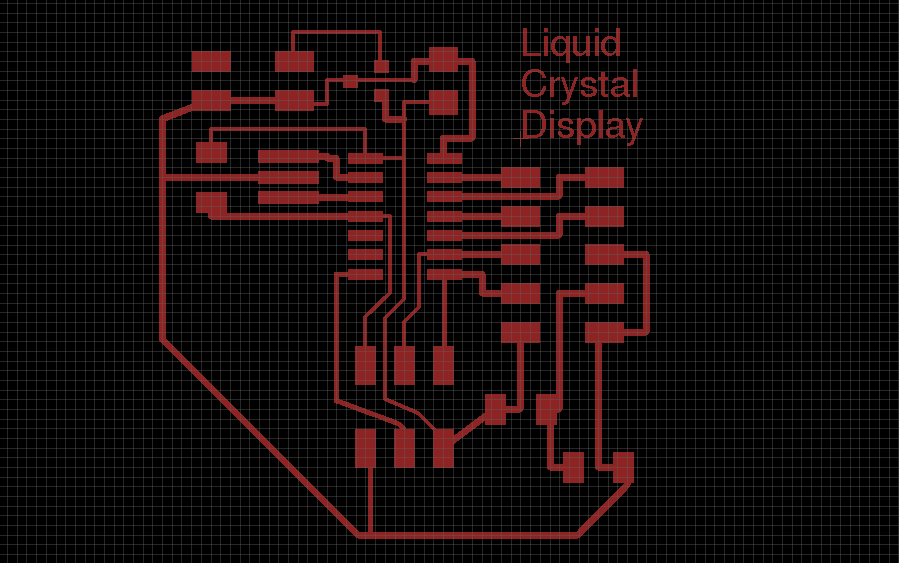
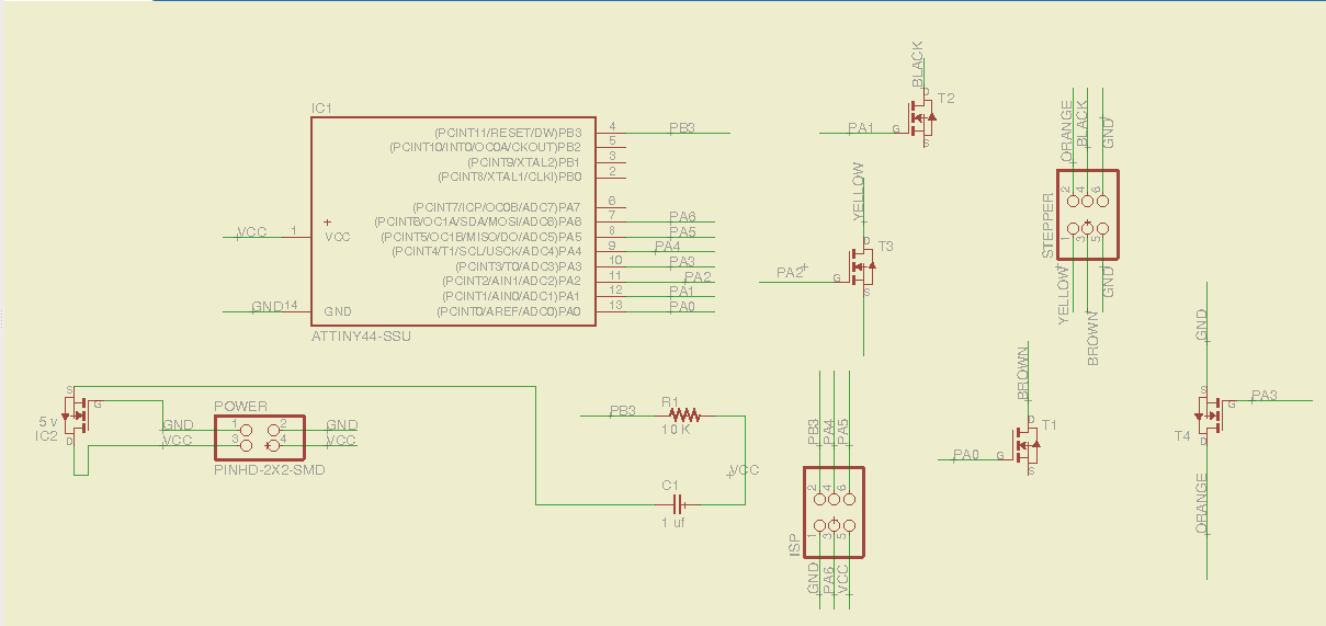
First I designed the board with Eagle, here you can see the schematic and the board design:
But I made a mistake in the design, two lines that should have been linked, were separated.
So first I tried to do a bridge, to link them togheter:
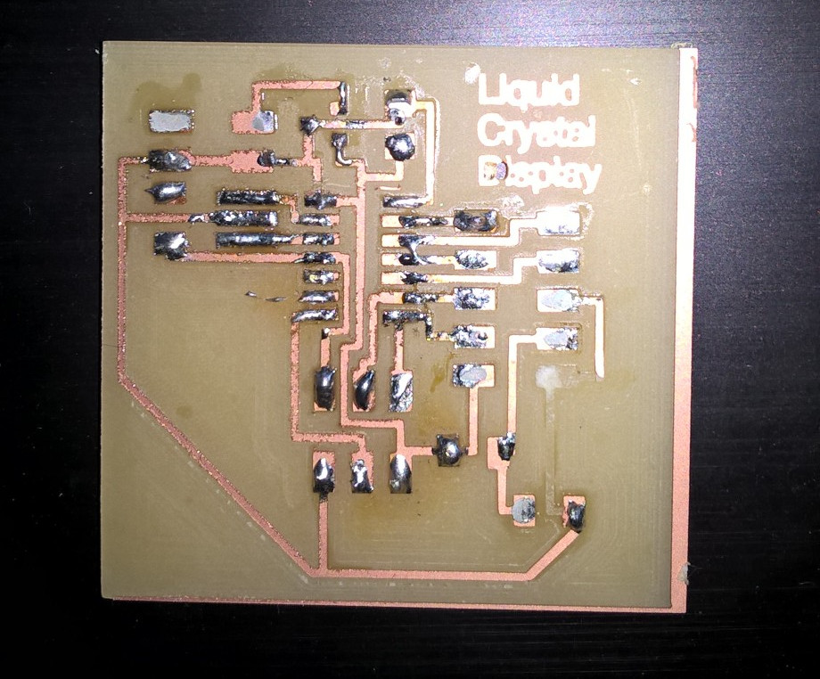
I tried to test it, but it didn't work at all. So I desoldered all the components:
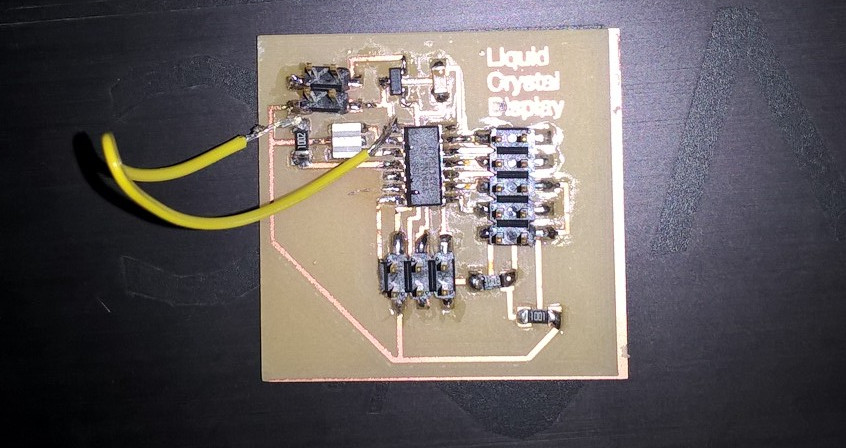
I re-did the eagle file, and I soldered it again, here's the result:
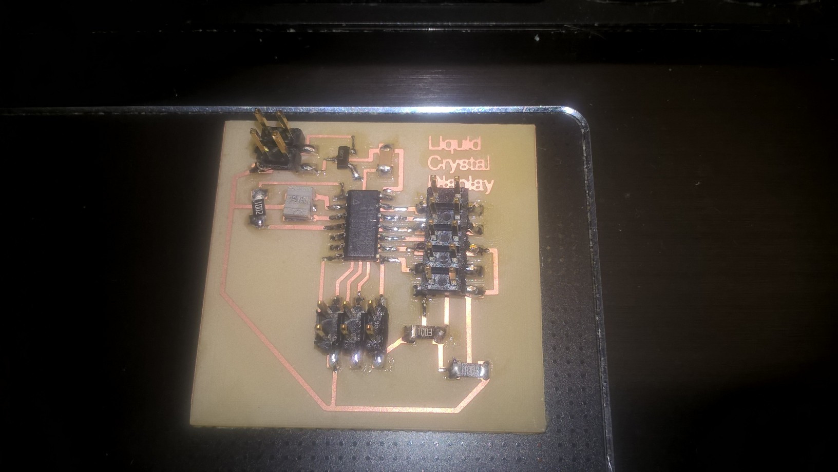 The wiring part was actually the most annoying, since I had to link and solder a lot of cables.
In order to do it right I looked for the data sheet of the LCD screen:
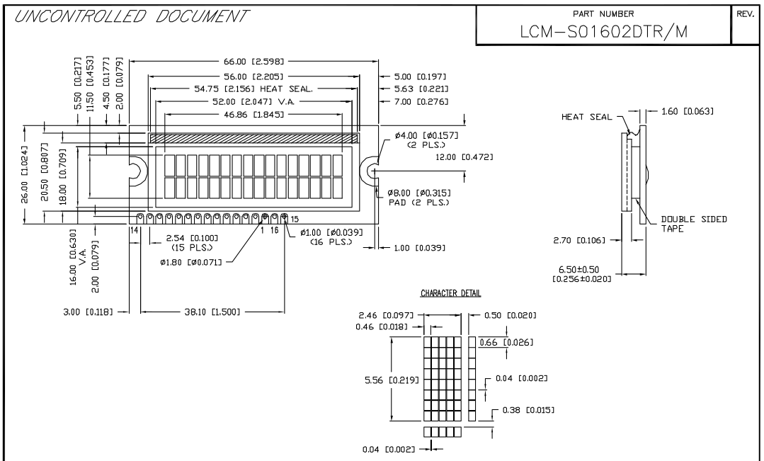

Once I knew everything I needed, I soldered the cables to the lcd display and I
flashed the program on the board, here's the lcd linked to the board:
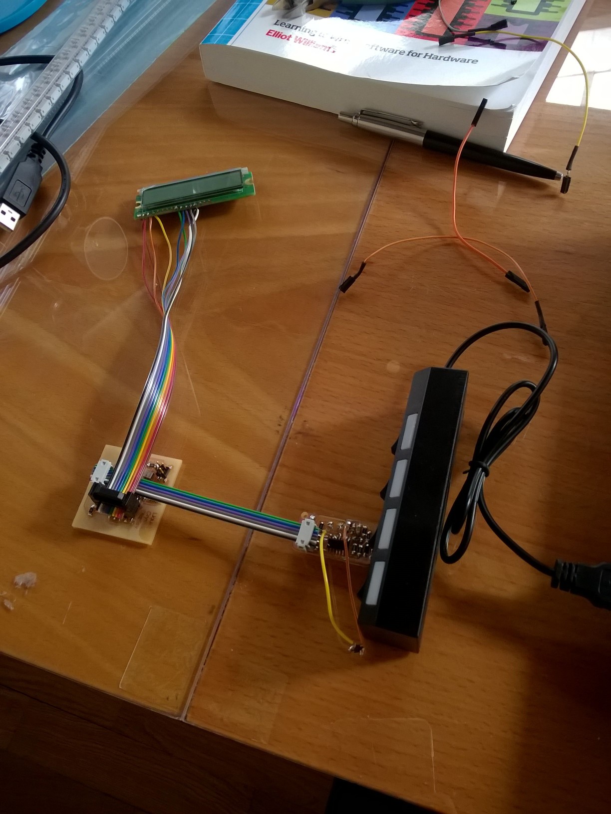
Here's the screen in action:
Stepper Motor
Since during Machine design we used threee stepper motors, I decided to do a stepper motor board. Once again, I designed the board with Eagle, here's the electric schematic and the board design: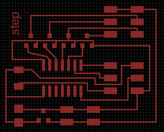
Here's the final result:

I flashed the program I've found on the archive and everything went fine, as you can see here:
but I had some hard time trying to connect the wires. It was the first time that I did something like this all by myself. I've looked for the datasheet of the motor, but I've just found one in chinese, so, in the end I gave up.
Conclusions
I took me a lot of time to understand how to properly use Eagle and do boards, but in the end it was one of the best weeks of my Fab Academy. Before this week I had a lot of troubles using Eagle, reading datasheets and trying to figure out how to fix problems.Download
LCD
Etching board .png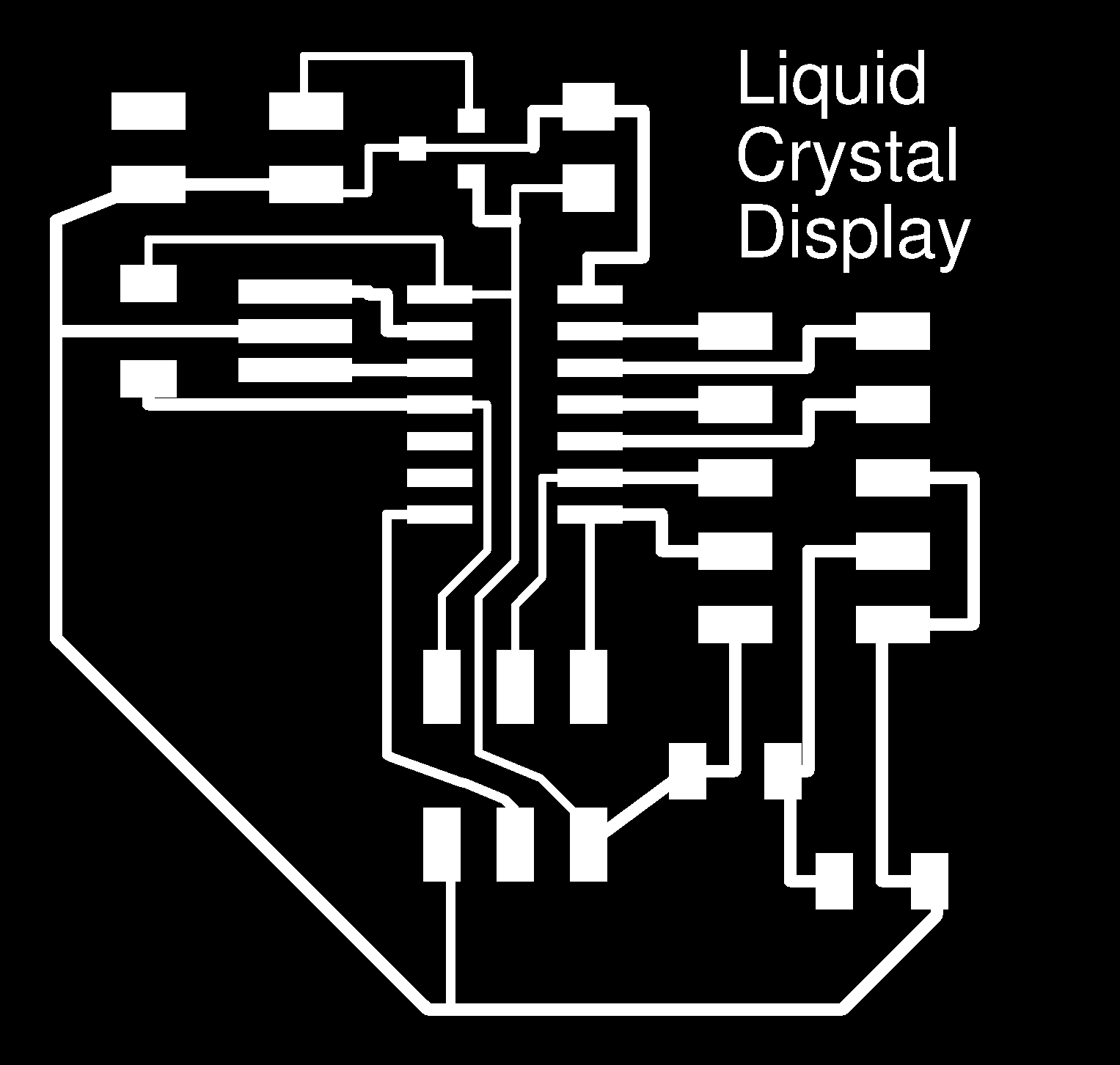
Cutting board .png
Eagle Board
Eagle Schematic
Stepper Motor
Etching board .png
cutting board .png
Eagle board .png
Etching board .png

This work is licensed under a Creative Commons Attribution-ShareAlike 4.0 International License.